by Dave Dennings
Screen printers often overlook the importance of maintaining a controlled screen making process. This report will focus on the importance of understanding the emulsion curing process and the impact it has on workflow efficiency and company profits. In addition, it will offer guidelines for determining proper exposure distances to assure uniform emulsion curing.
To understand why proper exposure distance from the light source to the screen is important, one must first understand the fundamental principles of an ultraviolet (UV) process.
A UV process involves the use of UV energy to bring about a chemical change in a reactive layer. An example is the conversion of a UV-curable ink to chemically change into a dry, tack free coating. In our case a dried emulsion coating chemically changes into a finished stencil resistant to various forms of inks, solvents and/or water-based materials.
Without the uniform presence of an appropriate source of UV energy, the coating is considered uncured. Once exposed to UV radiation, a polymerization reaction occurs within the coating and the coating cures.
A UV Process Requires Three Components
- Reactive Resin - By changing the reactive resin to accommodate a particular desired feature, the properties of the resultant emulsion can be altered.
- Photoinitiator - Photoinitiator is an important component of the UV curing process. Photoinitiator is blended with a reactive resin to create a UV-curable formulation. The photoinitiator is responsible for initiating the chemical reaction by converting the energy from a UV source into a free radical. This initiator causes the reactive chemistry to polymerize into a cured coating.
- UV Source - The final element of the UV curing process is a source of radiant energy in a spectral region appropriate for the emulsion coating. The energy required lies in the UV region of the electromagnetic spectrum and can come from a natural source such as the sun or an artificial source such as metal halide lamps.
Achieving Proper Cure
A UV curable formulation, whether it is an emulsion, ink, or adhesive, is considered cured when it meets the requirements of its intended application. These requirements typically include a minimal performance specification such as a specific hardness target for a hardcoat or shear strength for an adhesive.
Minimal performance specifications for emulsions involve chemical and mechanical resistance, as well as copying properties required to reproduce the intended image.
If, after exposure, an emulsion formulation fails to meet ALL the minimum requirements of acceptability, then it is not cured, or an incorrect emulsion formulation was selected.
Just as screen printers using UV curable inks must make sure UV travels through the inks entire coating thickness to achieve proper cure, so must they make sure UV travels through the emulsions entire coating thickness to achieve proper cure.
It is easier to achieve proper cure with UV inks because they use a linear curing process where the surface is passed under lamps that extend across the entire surface, providing uniformity of UV exposure in that dimension, while the motion of the substrate provides uniformity of exposure along the direction of travel.
The screen making process utilizes a flood curing process where the screen and exposure lamp remain static or stationary. Since the lamps and reflectors do not extend across the entire surface of the emulsion coating, placement of the UV light source in relation to the screen becomes critical to assure proper uniformity of exposure and stencil hardening. We'll discuss this in more detail later.
Defining Your Process Window
Proper exposure and stencil hardening requires a process window specification be in place to provide details on how to correctly expose the emulsion in order to cure it.
The process window refers to the range of exposure conditions that will yield a properly cured emulsion coating suitable for its intended application. Included in this specification should be details on the specific exposure unit and bulb including power level and bulb spectral output.
A UV radiometer can be used to measure the amount and uniformity of UV energy reaching the screen at various points across the screen.
The UV spectral sensitivity of direct emulsions generally falls in the wavelength range between 350 and 420 nanometers, therefore it is beneficial to use a radiometer that measures in the same wavelength range.
A UV source is actually much more than "just a light". Light sources today are sophisticated machines that can vary greatly in design. It is important to know what is right for your application. The ideal light source is one that can provide a consistent output of UV with the proper spectral energy distribution to interact efficiently with the emulsion.
Metal halide exposure units generate UV in a wavelength range that matches the spectral sensitivity of photo emulsions better than other types of exposure units. Manufacturers of these light sources offer a choice of bulbs with their system. It is important to understand the differences between the bulbs and how well they match the stencil system.
It is also important to understand the differences in focal properties of reflectors as they vary based on the design of the reflector. Some exposure units utilize a large square pebbly textured reflector to increase the effective coverage area, while others use a large round but smooth surface reflector. Still others incorporate a shutter and employ a small, smooth design. Manufacturers of exposure systems may even offer a variety of styles within the same design type. For example, wide, standard, and narrow versions of the same design type.
By using a UV radiometer, one can test the peak irradiance and uniformity of coverage by recording the measured responses of the radiometer in various areas of the coated screen ranging from top to bottom and from side to side.
Other process window specifications should include targets for emulsion: thickness, smoothness, drying and storage conditions and times, and the distance from the focal plane of the reflector to the surface being exposed.
Setting Exposure Lamp Distance
The instruction manual for the light source should provide information pertaining to setting up exposure distances unless the exposure unit is a self enclosed unit with a fixed distance.
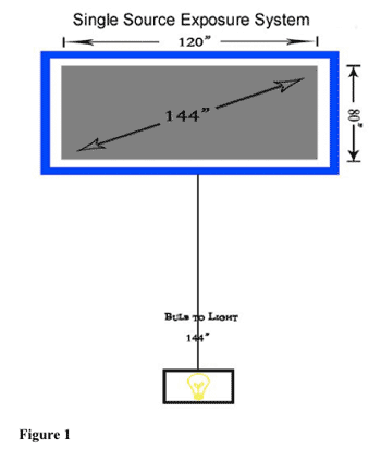
A typical rule of thumb is to measure the diagonal of the emulsion-coated area and use that as the distance from the glass of the vacuum frame to the safety glass of the lamp housing as illustrated in Figure 1.

It is important to verify that the distance established meets the process window for its intended application.
This can be accomplished by measuring the UV output at the perimeter of the emulsion-coated area of the screen and comparing it to the UV output at the center of the emulsion coating.
The area of the screen directly in front of the light source will have the greatest UV output. The UV output reaching the screen will begin to falloff as you measure further away from center of the lights direct path to the screen as the light has to travel further to reach the screen.
A 20-25 percent variance in UV energy between the center of the screen and the outer perimeter of the exposure area is often considered acceptable. The exact amount of acceptable drop in UV energy at the perimeter of the screen is dependant on the emulsion's exposure latitude and the printing tolerances required including run length.
The greater the variance in UV from the center to the perimeter of the emulsion, the greater the likelihood of encountering time consuming production slow downs. When the emulsion is not completely exposed in a uniform manor across its entire surface, it is more susceptible to scumming, pinholing and premature breakdown. It becomes more difficult to reclaim and leaves the mesh significantly stained.
The added time, labor, and materials incurred dealing with an improperly cured emulsion directly dips into company profits. The total cost to the company is significant. It is often not fully understood just how much time is wasted in inefficient, unproductive activity.
Time spent touching up excessive pinholes, dealing with press downtime, remaking screens, and consuming excessive amounts of reclaiming and ghost haze removing chemicals is a constant drag on the production workflow.
Periodically reviewing the screen making process and implementing a process window specification will help reduce inefficiencies while improving workflow and profitability.
A dual lamp exposure system may be warranted when working with very large screens, as the distance required for uniform coverage may be prohibitive to the throughput of screens. It is important to understand the inverse square law which points out that if the lamp-to-screen distance doubles, the exposure time necessary to achieve the same level of exposure quadruples.
In other words, if the lamp-to-screen distance is 40 inches with a calculated exposure time of two minutes, and the lamp-to-screen distance is moved back to 80 inches, then the proper exposure time is going to be eight minutes.
With vary large screens, using the common rule of thumb for setting exposure distance requires placing the exposure system at extreme distances as illustrated in figure 1.
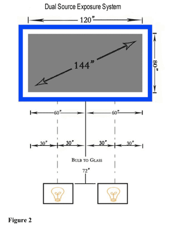
Therefore, large format printers may choose to use a dual lamp exposure system as illustrated in Figure 2.

Employing a Dual Source Exposure System for large format screens helps printers achieve uniform UV coverage while significantly reducing exposure times.
Conclusion
A fundamental understanding of the emulsion curing process and establishing a process window specification for exposing the emulsion will help reduce costly, time consuming bottlenecks in production while improving workflow efficiency and company profits.
Written by: Dave Dennings KIWO Inc. Product Manager Screen Making Products
If you have questions about this report or would like help in other aspects of the screen making process please contact me at KIWO Inc.
Telephone: +1 (281) 474-9777
Email: daved@kiwo.com

About the Author
- Phone +1-281-474-9777


